Motorola X31 Series Analog AM Radio

Funny thing about us collectors (radios or otherwise). Sometimes we collect so many things we forget about something that we have. I was recently looking over my radios and realized I had these two Motorola radios which I have never looked into…they’ve just been sitting on the shelf looking pretty for years. I knew that both were not working which is why I got them fairly cheaply way back when but I decided it was finally time to see what was up with them. But first, some background on these models.

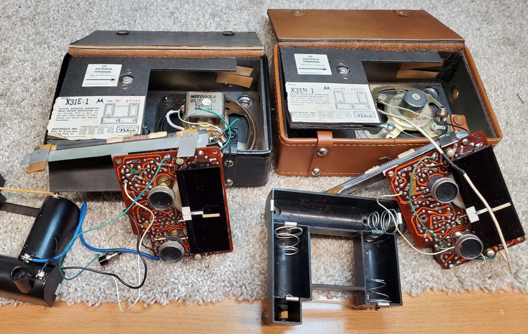
Description: The Motorola X31A/X31N Ranger was introduced in 1961 or 1962, the later X31A-1 (Gray), X31B-1 (Blue), X31E-1 (Black) and X31N-1 (Ginger) arrived in 1962. I have two of the -1 versions which dropped the Ranger name but were upgraded with an external antenna connector. The only service manual I have is the SAMS for the original version with Chassis HS-894 but my two later models appear pretty much the same except for that external antenna terminal. For simplicity I will refer to these as the X31 model.


This is an 8-transistor design featuring a tuned RF stage, three gang air variable tuning condenser and a decent-sized 5 1/4” ferrite rod antenna for potentially excellent performance. There is a 3” speaker labelled Motorola Golden Voice although the two radios I have contain different versions of the speaker. The only controls are On/Off/Volume and Tuning knobs and a novel Battery Life switch which I will describe later. Power is supplied by 4 C cells and there is a mono earphone jack. One thing I’ve mentioned before…batteries must have increased in size since the 60’s…my typical alkaline cells were an extremely tight fit, requiring lots of effort to install and remove. I really like the unique leather cover which can snap on the front for protection during transit or placed on the back for convenient storage…pretty cool. I found an old ad which revealed this was the top of the line of 3 similar models and retailed for $49.95 although at least one price I found indicated it may have sometimes sold for as low as $35 or so. I also remembered that it was featured prominently in the Robert De Niro movie “A Bronx Tale”. (Humorously, the producers added a whip antenna for effect…this was also done with the now well-known Packard Bell 8RT2 “Gilligan’s Island Radio”. Artistic license I suppose but I wouldn’t be a radio nerd if I didn’t point it out).

Putting them on the bench I verified that although the black one was completely dead the ginger set did make some noises as I tuned around…no real reception but at least the amplifier and speaker were good. The black one had a note inside from a previous owner which said “parts set” so I figured that one would be more of a challenge so I started with the ginger radio.
Disassembly was a bit tedious…these are nice radios but they exemplify designs that are not made for easy serviceability. There is a stiff cardboard cover which can be lifted out from the bottom then swiveled upward to expose the PCB. After removing two sheet metal screws in the battery box, the earphone jack and battery life test button nuts you can lift out the battery box, then three small hex head screws on the small PCB which can now be lifted out. Desolder the lead to the Antenna screw if so equipped. The issues are very short wires, some of which are fairly heavy gauge and stiffened with age which can easily break off the board, and you end up with wires from the battery box, speaker, earphone jack and battery test switch and the antenna terminal dangling and just asking to be broken free of the board which is a two-sided affair which Motorola called PCLair. I ended up desoldering most of these and using clip leads until I was ready to re-assemble the radio. Before re-assembly I replaced some of these with more flexible longer wires to make it all easier but it is tricky to position them so they don’t interfere with the battery box or cardboard cover during re-assembly. Don’t remove two Phillips head screws from the PCB…they release the black dial scale…you don’t need to remove it other than to access part of the PCB for other repairs.
First, I had to clean a slightly corroded battery spring. Luckily it was easy to remove from the battery box for cleaning with a little baking soda. The electrolytic caps all tested good and the only other problem the first radio had was a bad oscillator trimmer cap on the tuning gang. If I loosened it the radio began to work but I could not get it into proper adjustment without it shorting out killing all reception. I removed the tiny adjustment screw and cleaned between the two plates and tried repositioning the movable plate to no avail but before I dismissed this as an unrepairable tuning gang I decided to resort to an admittedly crude repair…I slipped a piece of tape between the two adjustment plates and when I replaced the adjustment screw, it could now be adjusted full range with no shorting. I don’t know if there was originally some insulating piece there or if the metal plate was bent, and it is interesting that the RF and Ant adjustment caps on the tuning gang did not have this problem, but the insulating tape worked perfectly and I must admit I was surprised that this repair actually worked! Everything tested good so all that was left was to do an alignment and re-assemble but once again the manner of assembly was a bit tricky, primarily routing the wires so they did not interfere with proper seating of the battery box and cardboard flap.

Above: Tape Prevents Shorting of Oscillator Trimer Cap
What about that unusual CD Antenna screw and the Battery Life Test switch? Both of these are a bit unusual. I have not yet found an Owner’s Manual but in advertising Motorola described the antenna connection as a “Civil Defense Antenna Terminal for emergency use in ‘fall-out’ shelters”. What’s technically unusual is that on most portable AM radios with such antenna connections there are usually two screws which are connected to both ends of a wire which is looped around the ferrite rod…usually about four turns. One end of this wire is for the antenna and the other is for a ground connection, without which the antenna will have much less effect. But on these radios Motorola decided to use only one external connection with the second end of the wire connected to chassis ground. It probably is not as effective as connecting to a true ground but I suppose it was to make things easier and I would guess that you could optionally connect the chassis to a ground to improve performance more.
The Battery Life Test switch is another unique feature. Most people might assume it is a dial light (and I wish it was) but what it does is to insert a 6800 ohm loading resistor into the RF circuit. If the batteries are strong there is no difference in sound but as the battery voltage begins to drop the switch will reduce reception letting you know the batteries have weakened. I decided to test this feature using a variable power supply and came up with the following results: With the total battery voltage dropped from 6 to to 5.5 volts (1.375 volts per cell) the volume dropped 3db when the switch was pressed. At 5 volts (1.25 volt per cell) it dropped 6db and at 4.5 volts (1.125 volts per cell) it dropped 7db. At any rate these analog sets use very little power and alkaline cells should provide hundreds of hours of play time. And of course, as with typical analog radios of the day the volume drops smoothly as battery voltage drops whereas modern electronics tend to work the same until they suddenly quit at their cut off voltage.

With the brown radio now working well it was time to look at the black set. As often happens it was a lot easier to deal with the disassembly after the experience I gained from the first set and I quickly discovered that the reason the radio was dead was a broken battery box lead from the PCB. Although I desoldered most of the connections I later replaced these wires with longer, more flexible wires as I had done on the other radio. The radio, all clip leaded together was still not working but once again I found that that same oscillator trimmer cap on the tuning gang could not be adjusted without shorting out. What are the chances two of these radios had this same unusual problem and why? I may never know but I now knew the cure and it worked just as it had with the first radio. I aligned and reassembled it…now it was time to play!
Performance: No big surprises here. As an 8-transistor design with a tuned rf stage and 5 ¼ inch ferrite rod reception is strong rating **** in the AM Mega Shootout. Even though there is no tone control the audio is clear and well-balanced. Listening to a variety of stations in addition to my home AM transmitter I found the audio pleasing overall. The X31 is rugged and attractive with a very nice slide rule tuning dial scale and as an analog radio it has that smooth natural tuning feel I love. Although it is not a Superadio it is among the better of the AM only portables from the 60’s I have seen…I like it!

You must be logged in to post a comment.