Panasonic RF-4900/DR49
Panasonic RF-4900 Restoration & EvaluationPANASONIC RF-4900

Sometimes someone brings a radio to my attention I had somehow been totally unaware of before. I guess this shouldn’t be so surprising considering the thousands upon thousands of radio models out there. Still, some models seem to slip under the radar…to be sleepers. One such radio is the amazing Panasonic RF-4900. Part of Panasonic’s “Command Series” produced between 1979 – 1983, there were four models in this particular series – the renowned RF-2200 (which most radio lovers are well aware of), along with the RF-2600, RF-2900 and RF-4900. This series has a striking external resemblance but there are differences inside that a prospective purchaser should be aware of.
")
The RF-4900 differs from the other three models at first glance because it is the only one which is a large, steel-encased table top design…indeed it measures 8” x 19” x 14” and weighs a hefty 20 lbs…considerably larger than the “lunchbox” sized portables comprising the rest of the Command Series. In fact you would think this is an AC only table top set but a quick look at the bottom panel reveals not one but TWO battery compartments which hold a total of 8 D cells which can power the radio away from AC power. There is also a 12 volt input jack along with the AC input receptacle on the back panel. Also rather unique in a battery operated portable – if you can call it that – the RF-4900 lacks a rod antenna which most portable radios routinely include. (Note that there were European versions of the RF-4900 known as the RF-4900LBS and DR49 depending on the country in which they were sold which were supplied with a rod antenna. More on those models later). But indeed, the standard US version contains only a ferrite rod for AM (MW) broadcast band. For SW and FM external antennas are needed but luckily the radio does a simply superb job with short pieces of wire for antennas. I will go into that in more detail later as well.
Other features of note include dial lighting that can be manually switched on or off full time (with a dedicated toggle switch) whether running on battery or AC power. A front panel calibrator knob – which operates equally easily with a fingertip or a small screwdriver – lets you precisely tune the digital readout (which functions on all bands) to precisely match the tuned frequency. The two speed tuning is simply the best I have ever encountered – pull the large tuning knob out for fine tuning or push it in to tune faster. With its little protruding spinner (see photo) you can spin from one end of any band to the other end of any band within seconds, yet home in on a specific frequency with ease and precision. Of all the analog multi-band portables I’ve used this one is among the fastest yet the most precise to tune – it is simply a delight to use. An impulse Noise Blanker often clears up reception nicely, Tuned RF, RF Gain Control, Dual Conversion (except between 1-6 – 3 MHz), TWO (!) 3 Gang Air Variable Tuning Capacitors, all built within a rugged steel case allow reception close to as good as it gets. A front panel Antenna Trimmer knob lets you match your antenna precisely for best reception. Linear Dial Scales keep you informed of where you are within each of the spread bands…, plus you can also elect to turnoff the Digital Display and tune around just like a fully analog radio. That display incidentally adds absolutely no additional noise I could detect…not usually the case. There are also jacks for external speaker, record out, and aux in, plus a dual purpose S-Meter/Battery Level meter.
But the RF-4900 really comes into its own when taken as a total package. In many ways it represents the best of both worlds, offering all the benefits of fully analog operation (no chuffing, muting or jumping when tuning) with all the benefits of digital readout, accurate to 1 KHz at all frequencies. Its performance is among the best I have ever seen and I will put it through its paces and compare it with some other reference radios after I describe what it took to get it there.
Finding an RF-4900 on eBay: Evidently these were manufactured in relatively great numbers because since I became aware of the model I have found several coming up for auction each month. Luckily they were well made and most have stood the test of time with only minor issues. When you find one you are interested in ask the seller some friendly but probing questions – this is good practice in general because I’ve found that good sellers will communicate freely and openly. If you can’t get a friendly and clear answer before the sale, how do you suppose that seller will treat you after the sale if you have a problem? In particular I would ask if the radio seems to be working properly on all bands, if it has the AC cord, if it has both battery covers etc. Such questions should elicit fairly clear answers from any seller I would care to do business with.
Intermittent Switches: Just as with its better-known brand-mate RF-2200, the RF-4900’s seem to usually suffer from dirty switch problems. Slightly dirty switches may manifest themselves merely as noisy when operated but if bad enough the entire radio may seem totally dead with no reception on several or all bands. Usually it’s not a difficult problem to fix but special care has to be taken and I’ll outline how I did mine later on.
")
Main PCB Showing 4 Large Bandwitches
When I finally received my radio, sure enough it seemed deader than a doornail. When I plugged it in and turned it on the lights came on and there was a slight hiss from the speaker, and a loud crackle when I turned the volume or tuning knobs, but no reception on any band except FM which seemed to be working at about half of what I would expect. Signals were weak ( there was no antenna on it) and volume was weak as well. I hoped the switches might be the culprit and as I aggressively worked them I got some glimmers of sound on AM and SW but nothing much. It was also rather filthy looking as if it had been stored in a barn. (See before and after picture below). Externally it was easy to clean once disassembled although cleaning the interior, including the top of the PCB took lots of patience and time. For that I used paper towels and cotton swabs with 91% isopropyl alcohol to physically remove as much dirt as I could not only for general appearance but to help avoid future problems. I soaked the knobs in soapy water for a few minutes then cleaned them with a toothbrush…perfectly cleaned knobs really look sharp and can make a huge difference in the overall appearance of a radio.
")
This Exterior Dirt Was Easy To Clean
")
Much Better!
Removing the top cover was an experience…no less than 35 screws hold this baby together. Yes, your hand will literally get tired unscrewing all those screws. Also I discovered that four plastic shrouds where the front panel handles mount snap off revealing yet more screws underneath…just an amazing number of screws used here. The bottom panel was easy to remove as well as the front panel…just more screws and it all comes apart easily.
")
Serviceability Is Excellent
The interior is impressive. Two large PCB’s dominate the architecture, along with the two separate tuning capacitors…one above and one below the circuit boards. The two-speed mechanical gearing used for the SW 2-8 tuner is incredible…smooth, easy and precise…no backlash or play at all. I connected a short length of wire to the SW 2-8 antenna terminals on the back and powered the unit up again and as I tried the SW bands and worked those switches, the more I worked them the more I was getting out of the radio. It was obvious the switches needed to be cleaned before anything else could be done. Ideally I would have liked to remove them and taken them apart but I decided to try an alternative method as the removal and disassembly looked like a lot of work. I didn’t want to simply spray them with tuner cleaner in place…they were way too far gone for that, and the amount of fluid needed to flush them clean would have resulted in lots of liquid all over the radio, virtually guaranteed to damage several components, most notably the ceramic vari-caps used for alignment. More damage is caused by the mis-use of spray contact cleaners than many people like to admit.
I decided on an unorthodox approach – I carefully used duct tape and plastic sheets to isolate the switches from the rest of the chassis so I could flush them heavily with 91% isopropyl alcohol. I wanted to run enough fluid through them so as to remove the built up dirt as much as possible. I used compressed air to forcibly extract as much fluid as possible and repeated the application and air drying. After that I followed up with just a small amount of De-Ox-It…my recommended switch cleaner. Then I cleaned up again with alcohol to remove any traces of the De-Ox-It outside the switches before removing the tape and plastic. To my relief the PCB was still dry and somewhat to my amazement…the radio now worked! I mean it worked very well. Now tuning on all bands the radio seemed quite sensitive with many signals. I cleaned the rest of the switches and controls in the usual way and all responded perfectly with no trace of static or intermittency with any of them. *(Since originally writing this article I’ve had the chance to work on several more RF-4900’s and am currenlty working on restoring a DR49/RF-4900 LBS. In two cases I ended up removing one of the bandswitches…the largest one which which is also the easiest to remove…to clean it manually. It’s contacts were black with grime but cleaning restored normal operation. Removing, disassembling and re-assembling these long multi-pole switches is a bit tedious but not really that difficult if you work carefully).
The tuning gangs also needed cleaning badly…they were very intermittent when rotated. Generally compressed air is all that should be needed to clean them but in the case of a filthy radio like this one more drastic measures are needed. What I do is flush the plates with alcohol, then blow as much of the liquid out with compressed air as possible. Usually repeating this once or twice will get the desired results…just be aware that even after drying as well as you can with compressed air you usually have to wait for some time…perhaps 15 to 30 minutes for the last traces of moisture to evaporate before normal operation is restored on all bands. You should also lubricate the tuning gang bearings with a lubricating contact cleaner or fine oil…there are electrical contacts here that can also be noisy if not treated properly.
")
Front Panel Calibrator Top Center
I noticed though that the frequency readout did not track very well from band to band on SW 2-8. That is, if I adjusted it properly for some bands, it was way off for others and in fact was barely able to reach proper adjustment when rotated to one extreme of its range. I decided that, as there seemed to be no other major issues with the set, it was time to align it and see if that cured this annoying issue. And with that began one of the more frustrating journeys I’ve taken while restoring an old radio.
")
Great Access For Control Cleaning
The first step in the alignment is the AM IF stage…the very first adjustment point is designated as T4, the first IF. I was gratified to find that it was very close to its 455 KHZ point, and as I proceeded through all 5 IF adjustments they were all quite close but there was some overall improvement as there often is with a 30 year old radio. Perfectionist that I am I decided to go through them a second time just to be sure each was absolutely peaked, but when I turned that first IF its core cracked and the set went dead. My RF generator’s tone was replaced with a quiet HISSSSSSSSSS. This is a bad moment that many technicians can identify with. Usually, if you are using proper alignment tools (which I was) and if you don’t force a stuck core (which I wasn’t) this should not happen. In this case the core did not appear to have been stuck yet with very little effort it was toast. I removed the IF can from the board and carefully took it apart…the core fell out in many tiny pieces, hopelessly beyond repair. Now what?

1st IF Transformer T4 Lower Right
As it happens I have a parts chassis from an RF-2200…a radio from the same era and series as the 4900, and a quick look at the service manuals confirmed that indeed the 2200 used two of these same transformers. What luck! My enthusiasm was brief though…after comparing my 2200 and 4900 I discovered that the manual was not correctly identifying the transformer in my 4900…it had a different number stamped on it and physically was a bit different as well. (See note) I tried the 2200’s can in the 4900 and it did not work…still nothing but hiss. A friend of mine determined that they had a different inductance in one of the coils and a different value cap inside as well. Clearly this was keeping the replacement transformer from resonating. Although it might technically be possible to compensate for these differences, the right approach was to obtain a proper replacement. The part was long since discontinued by Panasonic (I verified that) so the only source would be a parts donor RF-4900. Since my friend was interested in getting one of these sets for himself we decided to go in together on a parts set and after a few weeks we had one. The replacement transformer restored normal operation for my set, so all that was needed (or so I thought) was to finish the alignment and button it up. As they say…best laid plans.
(Note): A Comment On Service Manuals. It is worth noting that over the years I have found many errors in service manuals, whether from the original manufacturer or from after market sources such as Sams or Riders. Sometimes they are outright errors; other times there may have been production changes along the way or there may be variant models with only subtle differences.. Some manufacturers provided updates, some didn’t, but with vintage gear you never know if there may have been updates you don’t have. For radios that are important to me I try to obtain every version of service manual available from every source and covering every variant model, but even if your manual does not agree 100% with the unit in front of you, you still need one for any serious work. You may be able to “fly blind” with a basic AM only radio but not with a complex multi-band receiver.
I ended up going through most of the alignment procedure twice because there is some ambiguity in the description of it. In essence, for each band, Panasonic tells you to tune to a specific frequency, but then there are oscillator adjustments for each end of each band. Well…if you’ve already tuned to the specific frequency, why would you re-adjust the oscillator adjustment, which throws you off the correct frequency? It finally dawned on me that they did specify that the digital readout should be turned off during the alignment. The reason is that they want you to ignore the frequency readout or analog dial indication at this stage and do a rocking adjustment, which I’ve described before. Basically, for each frequency limit you tune to the desired frequency, then “rock” the tuning gang while peaking the oscillator adjustment to achieve maximum gain. This is crucial. This not only restores maximum sensitivity across all bands but also brings the digital readout into proper calibration across all bands. Once I did this properly the set was exceptionally sensitive and the front panel calibrator for the digital display almost never has to be touched…plus it sits right in the center of its range. This is the way it is supposed to be.
")
This Is One Beautiful Radio!
Now the RF-4900 was performing like a champion…with just a short wire attached to its terminals it was pulling in weak daytime SW signals as well as my reference radios and even better in many cases. This radio was one I would have to check out thoroughly to fully gauge its performance. But then…another glitch.
I had put the radio into daily use in my listening post where, in addition to SW band scanning and comparing it with other radios, I used it daily to listen to my local AM station on 1080. I had been happily using the radio this way for several days when one day, without warning, 1080 suddenly disappeared. I looked at the set and its digital readout now indicated 1154 KHz! The analog dial still sat at approximately 1080. I tuned downwards and found my station again but not until the analog scale had reached close to 1000 KHz, and the signal was now somewhat reduced in strength. I tuned back to 1154 and gently tapped the side of the radio and with a slight “pop” it snapped back to 1080. I also ascertained that this problem was affecting only the AM band which is a big help localizing an intermittent defect.
Back to the work bench it went. As I probed around the AM board I was able to make the frequency jump back and forth between the two frequencies briefly…then, it went back to normal and would not go out again. I decided to take some measurements to help isolate the problem when it came back (because I knew it would come back) , so I measured the upper and lower limits of the AM band while it was working properly and found them to be 511 to 1730 KHz. It took three days of operation before it went out again. When it did I checked the top and bottom limits of the AM band again and found it was now 530 to 1990 KHz which meant the error was far greater at the top of the band than at the bottom. This helped me isolate the area of the defect to the AM band oscillator adjustment as the most likely culprit. I suspected the plastic vari-cap trimmer might be flaky as they sometimes are but as I rotated it, it adjusted perfectly smoothly. But if I pressed on its outer case the radio would start acting up so I decided to reheat its connections even though they looked solid. That was it…no more intermittent. I re-adjusted that pot to restore correct alignment and the set has been purring happily along for months since. Often when finally resolving a problem like this I wonder if this is what made the original owner stop using the radio and put it away.
")
AM Ferrite Rod & External Antenna Connections
One other alignment note: The ferrite rod on the back of this set has a convenient adjustment core accessed through a hole in its end…much more deluxe than sliding a coil along the rod as in most radios – a very nice touch! This rod should be swiveled down and away from but kept parallel to the back panel when adjusting its core. This will allow maximum AM reception because this rod interacts with the steel case when it is swiveled toward or away from it. Whatever position the rod is in when it is adjusted will be the position which later yields maximum sensitivity, so although the fact that it can be swiveled is nice, and may help in a particular situation, be aware that this rod works best when in whatever position it was in when it was adjusted. A quirk to be sure but one to be aware of. If you are not aligning your radio you might check to see which position gives the best performance with your set…it may have been in a different position when adjusted.
Use Tests & Comparisons: All work completed it was time to sit back and enjoy the ‘4900. First I decided to compare it with my hottest AM and SW portable radios; namely the Panasonic RF-2200 (on AM) and the Sony 6800 (on SW). Somewhat to my surprise the RF-2200 edged out the 4900 as king of the hill for AM weak signal daytime reception with built in antennas. Although the RF-4900 is an excellent AM radio, the RF-2200 is able to retrieve weak daytime AM signals will slightly less background hiss. No big surprise really…the RF-2200 has beat every other radio I’ve ever compared it to for this. They were fairly close, but there has to be a winner and the RF-2200 is it. This is also borne out by Panasonic’s own specifications (see the Command Series Brochure below) which shows better AM sensitivity on the RF-2200.
")
RF-2200 (Top) Sony ICF-6800 (Center) RF-4900 (Bottom)
On SW however the tables were turned. The RF-4900 greatly out-pulled the RF-2200…it only took a short time to realize that signals I couldn’t even find on the ‘2200 came in quite nicely on the 4900 – they’re in different leagues on SW. This too is borne out by Panasonic’s specs.
Next came the Sony 6800. This radio is my reference for SW sensitivity off the whip antenna and is widely known for being a hot radio on SW. Well the RF-4900 has no built in SW antenna so I used about 12 feet of wire hidden behind a picture on the wall behind it. I didn’t expect much of the Pan in this setup; after all, it’s supposed to be connected to an external, low impedance antenna…my short indoor wire would hardly be a proper match for it. What a surprise then that the Panasonic easily matched the Sony on every week, daytime SW signal I could find on every band! This Panasonic, which I had never even heard of before, was at least as good as one of the world’s most sensitive SW radios – amazing! By the way, I tried that same short wire on the Sony 6800 but it never worked as well with the wire as it did with its whip antenna…evidently the wire just was not a good match for it. The RF-4900 also exhibited excellent AGC characteristics, which means that fading signals sounded as stable and clean on it as on my best radios and again, better than most.
Well…if this radio can do so well on a short piece of wire, how would it do on an real external antenna compared with radios known to excel in that configuration? To find out I next compared the RF-4900 with my Grundig Satellit 800, Eton E1 and Sony 6800 radios, with each connected to either a 50 foot random wire antenna or a Wellbrook ALA330S loop. Again I was impressed with the Pan. Here the results were a bit closer. Because both of these antennas deliver much more signal than any short indoor antenna, signal strength was less of an issue. All three radios seemed to have some signals they did better on than the others but I would be hard pressed to declare any of them a winner. Certainly with synchronous detection the Eton and Grundig sometimes had a tremendous advantage over any analog radio. Additionally, if I were a serious SSB fan the PLL tuned radios have an extreme advantage over most analog radios. But discounting sync or SSB the Pan certainly held its own with its more modern competitors and essentially if I could hear a signal on one of the radio I could hear it about as well on any of them. That’s saying something!
I also compared them at night when there are many stronger signals. In these tests both the SAT 800 and E-1 had a slight advantage over both the RF-4900 and Sony 6800. The E-1 and SAT 800 are somewhat less sensitive but also have a much higher RF input capability that prevented any signs of overloading. Both the Pan and Sony showed some overload, although it was generally manageable using their manual gain controls.
")
Two-Speed Tuning With Spinner
Ergonomics: Every radio has pros and cons in this area and the RF-4900 is no exception, and one aspect of its design might be considered a plus or a minus depending on how you are going to use it – I’m referring to the antenna input arrangement. The back panel features individual spring clip inputs for FM, SW-1 (1.6 – 3.0 KHz)/AM, and both spring clips and SO239 jack for SW 2-8. If you have separate AM and SW antennas this arrangement is a plus, but if you have an all in one antenna you will have to use a splitter or switch to connect it to both inputs. Since there is no self-contained FM antenna there are two easy recommendations; either use a simple piece of wire about 31 inches long or use a dipole FM antenna for greater gain. You will get amazingly good FM reception on this radio even with just the single piece of wire…certainly the FM is so good it will outperform most portable radios with their whip antennas on FM.
Tuning Accuracy & Stability: In the world of analog radios the RF-4900 is very stable. For standard AM use you will seldom note any drift whatsoever. It is spec’d at +/- 1 KHz which is excellent…after a 10 minute warm-up period any drift is negligible. The digital readout also seems very stable – as I mentioned earlier I seldom have to touch it at all. However this is not my choice of radios for SSB. SSB tuning is so critical that no analog radio matches a more modern PLL digitally tuned design for rock solid stability and ease of tuning.
Sound Quality: I hate to say it but this is one area where I think the ‘4900 could have been a bit better. Its sound is ok and certainly nothing about it is irritating, but it is a bit lacking in the frequency extremes compared with several other radios I compared it to. Especially given the huge size of the box, this could have had a much better speaker in it. The audio output quality from the jack is excellent so it appears that the speaker itself is the limiting factor. This could be an area of experimentation if I could find a better speaker that would fit.
Other Versions & Their Antenna Arrangements: As I mentioned at the outset there are variants of the basic US version RF-4900. They are the RF-4900 LBS and DR-49, both essentially identical but sold in different countries…the DR49 being the UK version, the RF-4900LBS was sold in other European countries. Each offers multi-voltage operation, plus long wave and a whip antenna which feeds all bands except AM as on most other portable radios. Comparing the schematics of those versions with the US version there is additional input circuitry to allow the whip to work in this manner, plus an additional ferrite rod on the rear panel for LW reception. Otherwise the radios should be similar or identical.
Panasonic Command Series Brochure
Panasonic Command Series Brochure Specs
Conclusions: So why is the RF-4900 such a sleeper compared with its sibling the RF-2200? I can only guess. For one its original selling price of $399 – $479 in 1979 is equivalent to over $1400 today…that probably ensured that many more 2200’s were made and sold than 4900’s. Add the fact that the 4900’s superiority was more in SW whereas the 2200’s forte is AM and the reality that more multi-band portablesare actually used for AM than SW might have made a big difference. And of course the portability factor…although the RF-4900 is “portable” by some definitions (it does run on batteries or external 12 volt DC power), its sheer size and unusual antenna arrangement seems to mandate primary use as a table top set. If you are lucky enough to obtain one I suggest using 10 to 12 feet of wire for the SW bands and a 31” wire for FM. As a table top set it has become one of my reference radios and is one I truly enjoy using. The RF-4900 just gets so much right!
Questions or comments? email me at: radiojayallen@gmail.com
*Notes On Panasonic’s Command Series
There were 4 models in this series including the RF-2200, RF-2600, RF-2900 and RF-4900. Looking at Panasonic’s sensitivity specs we can see that they agree precisely with my findings that the RF-2200 is indeed still the king of AM portable radios, but the RF-4900 is incredibly more sensitive on SW. While I always take such specs with a grain of salt because different measurement methods can yield wildly different results, I usually find that manufacturer’s are at least consistent among their own models.
Other things you should know is that the RF-2200 and RF-4900 use quality air variable tuning capacitors while the RF-2600 and RF-2900 use cheaper PVC (plastic-encased) variable caps which subtly compromise performance and may deteriorate over time.
—————————————————————————————————————————————————————————————-
UPDATE: Since I wrote the original article I have acquired an RF-4900LBS/DR 49 which is the European version of the RF-4900. It ended up requiring more work than my original RF-4900 and I learned more about how these radios work along the way. The RF-4900 remains one of my favorite vintage receivers…the version most of us are aware of here in the US lacks a few extras found on the foreign models and for some reason Panasonic chose odd ways to differentiate them.
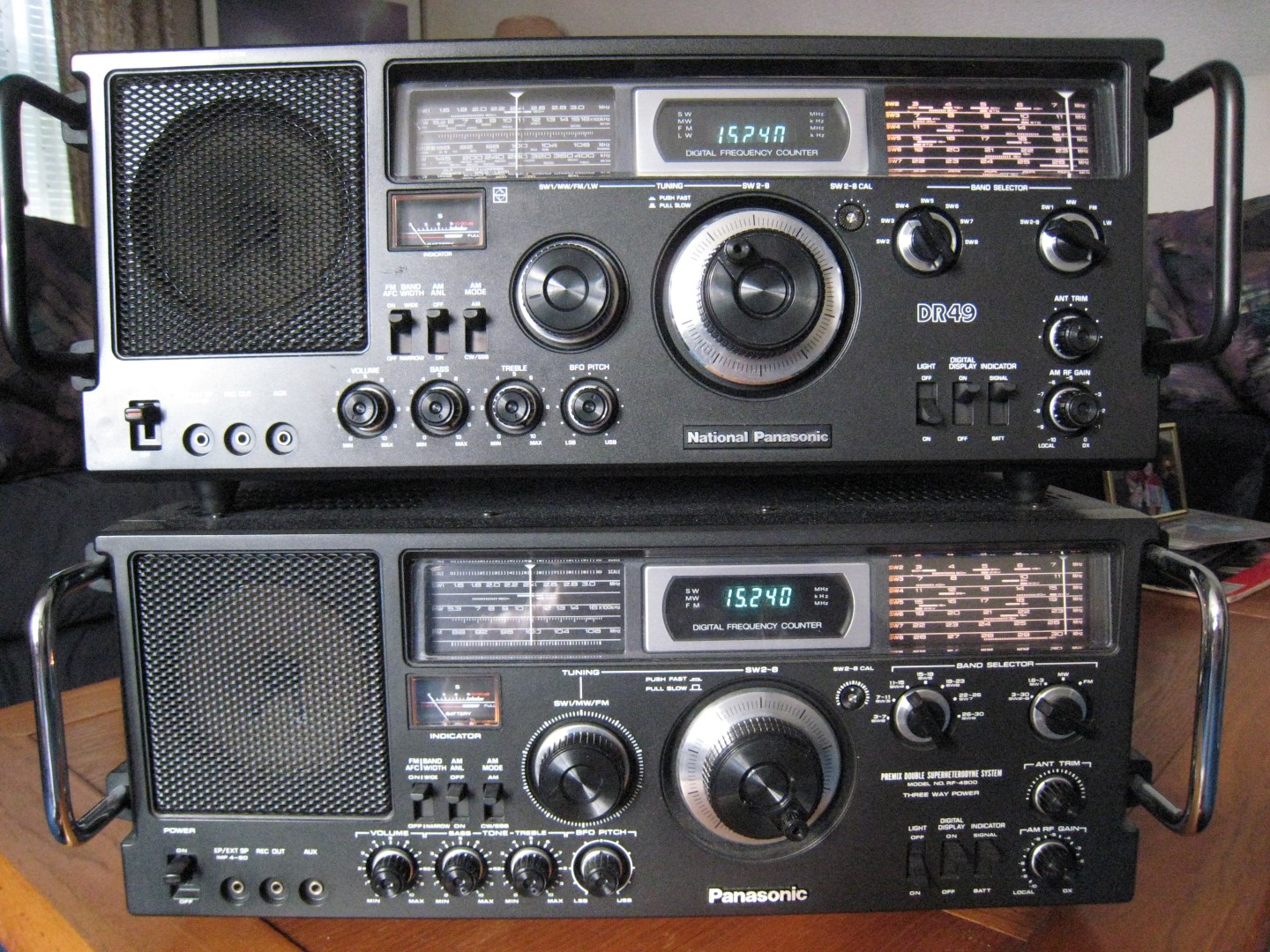
Top: DR49/RF-4900LBS – Bottom: RF-4900 US Version
The models for all countries other than the US were called the RF-4900LBS or LBE and they differ from the US version in that they include the LW/Longwave Band (perhaps what LBS stands for), a dual voltage 120/240 Volt AC power supply, a European standard Din Audio input/output jack and associated Radio/Phono switch and a built-in whip antenna and matching circuit for SW 2-8 and FM…the US version requires an external antenna for all bands except AM. These versions also dispense with the spring loaded antenna clips in favor of standard European jacks, although all versions have a standard SO239 jack for SW 2-8. Finally the LBS/LBE versions sport matte black rack handles rather than chrome, but either way I love the looks and feel of these radios.
To add to the confusion the DR-49 version is marked DR-49 on the front panel but is actually an RF-4900LBS as marked on the back panel, and some of these DR-49’s are labeled National Panasonic on the front while others are labeled Panasonic. I have never seen a service manual marked DR49 but I do have the RF-4900 LBS manual which matches my radio. I also have a picture of an RF-4900 LBS/LBE Owner’s Manual but have not seen an LBE radio.
While I can certainly understand the omission of Longwave for the US market I don’t understand why the US version lacks a rod antenna for SW and FM as almost all portables have one. My guess is that it was a marketing decision to make the radio seem more competitive with table top models than portables, yet it does run on batteries, and the inclusion of the rod antenna and simple matching circuit for it couldn’t have been much of a cost factor considering how complex the design of the radio is in general. I suppose we’ll never know.

Top: DR49/RF-4900LBS – Bottom: RF-4900 US Version
This DR49 came to me as a gift…a basket case, from a radio collector friend who was not able to get it working…he told me he received it in this condition and had no history on it. While the unit was cosmetically near mint the interior revealed that much work had been done on it…primarily what I saw was lots of bad soldering which had lifted the printed PCB patterns in a few areas, particularly around the largest of the 4 band switches, S 4. Symptoms included the usual intermittent switch issues, dead FM, an AM band that only tuned to about 1000 KHz (rather than 1600+ KHz), and generally poor performance overall.
Preliminary trouble-shooting was tricky because of the number of problems…one always tries to deduce if there are any areas of commonality among multiple issues. Since the bandswitches were badly intermittent and are often a cause of trouble, I first tried cleaning them with De-Ox-It D5 spray, which often works miracles. Although there was some improvement there was still some intermittency and the three primary problems were still there, so I decided to remove that big switch and clean it manually – quite a tedious job. Still no go…although it was much better it still had a dead spot on SW2. However I decided to tackle the other problems to see if I could make any progress.
First the dead FM issue – there was nothing but hiss across the band and the display showed 99999. I suspected the FM oscillator was not working but all the voltages were in spec. Luckily I have a few friends who are electronics specialists…engineers who are also vintage radio enthusiasts. One of them happens to own a junker RF-4900 we have used as a parts donor set in the past…it contributed an IF transformer for my original RF-4900. We thought the oscillator transistor was the most likely place to start but replacing it made no difference. Next we replaced a coil associated with that transistor and the FM sprang to life. Interestingly the coil seemed ok when we measured it outside the radio so we installed it in the parts radio as a check and it did not work so we know it was bad. One problem solved.
Next the AM band coverage problem – that turned out to be a bad cap in the AM oscillator circuit. Panasonic describes this as a “styrol” cap…it appears to be polystyrene. These caps are known for temperature stability so it makes sense to see them in an oscillator circuit. I have since uncovered a few bad ones in this radio…since these are not considered to be problematic in general I wonder if Panasonic happened to obtain a bad batch of them.


Now all that remained (I thought) was that dodgy bandswitch which had already been removed and cleaned. I obtained a replacement from the parts set, disassembled and cleaned it. After re-installing it and doing some jumper repairs to the PCB where this switch is soldered all seemed well…until I started to go through the alignment procedure. The bottom of the SW2 band (3 -7 MHz) would not peak properly…its associated coil L9 had no effect and sensitivity was way down in this band. We replaced that coil to no effect…the problem turned out to be another styrol cap – C40. We replaced it with a cap from the parts set and it worked for a day, then went out again. This time I used a new cap in its place and the problem was finally resolved permanently…L9 now peaked as it should and normal sensitivity was restored. Once again I thought I was done…but not quite.
I noticed that three of the shortwave bands, SW3, 6 and 8 had a major error with the digital display…it was off by a large margin and way out of the range of the front panel calibrator knob. While the display generally varies by no more than +/- 1 KHz, these three bands were off by about 20-25 KHz…clearly not anywhere near specification. But only on three bands…SW3, 6 and 8. That seemed pretty odd until one of my friends pointed out some information contained in the Technical Description booklet which is an extra booklet not included with the Service Manual. Sometimes these are called Theory Of Operation booklets but whatever they’re called, they walk you through a description of how the various circuits work with block diagrams, flow-charts and written explanations that go beyond the basic service manual.
It turned out that there is a separate oscillator adjustment for those three bands which, by missing an important step in the alignment process, I had misadjusted. Once I realized my mistake all was well and finally the “basket case” radio was 100% operational. Whew!
I next compared it with my original US version RF-4900 and as expected performance seemed identical as it should. I will say that the rod antenna and its matching circuit seems to work extremely well. Although I generally use these radios with some sort of external antenna it seems that the addition of the whip antenna just adds more flexibility.


The RF-4900 remains one of my favorite vintage analog radios. It is extremely sensitive, has clean pleasant audio, its tuning is fast and easy to maneuver among bands and to move from one end of a band to the other in a flash, and is enhanced by the small spinner knob on the main tuning knob, while the slow speed tuning gives great control for fine tuning. The only negative I would mention is that although this radio has a BFO for SSB reception it is not stable enough to make this practical…I do not recommend this radio for SSB other than in a pinch. But overall the RF-4900 is a solid tank of a radio…a battleship that really floats my boat.

You must be logged in to post a comment.